Cephalometric Angular Measurements of the Mandible Using Three-Dimensional Computed Tomography Scans in Koreans
Article information
Abstract
Background
We conducted this study to analyze the values of the key cephalometric angular measurements of the mandible using 3-dimensional (3D) computed tomography scans.
Methods
In the 106 enrolled patients, a 3D cephalometric analysis was performed to measure the angular variables of the mandible. These values were compared between the two sides and between the two sexes.
Results
The frontal measurements revealed that the mandibular body curve angle was larger on the left (Lt) side (right [Rt], 141.24±7.54; Lt, 142.68±6.94; P=0.002) and the gonial angle was larger on the right side (Rt, 134.37±8.44; Lt, 131.54±7.14; P<0.001). The sagittal measurements showed that the gonial angle was larger on the right side (Rt, 134.37±8.44; Lt, 131.54±7.14; P>0.05). Further, the transverse measurements revealed that the mandibular body curve angle was larger on the right side (Rt, 140.28±7.05; Lt, 137.56±6.23; P<0.001).
Conclusions
These results provide an average of the mandibular angular measurements for the Korean population, establishing a standard for determining surgical patient groups and outcome evaluations in the field of mandible contour surgery.
INTRODUCTION
The chin is one of the major features forming the overall facial profile, and there is an increased demand for jaw bone surgery for both functional and aesthetic purposes [12]. Obtaining a preoperative measurement of the anthropometric parameters for craniofacial or orthognathic surgery is important for performing an accurate preoperative assessment, planning surgery, and evaluating the postoperative outcome [3].
In 1922, Pacini [4] first introduced the use of radiographic images for measuring facial anthropometric parameters. Broadbent [5] further developed this method to create the modern cephalometric analysis in the 1930s. Even recently, conventional cephalometric analysis has been considered an important clinical tool in the planning and evaluation of orthodontics and orthognathic surgery, but it has several well-known limitations such as projective displacement, rotational errors, and linear projective transformation [6].
To overcome these limitations, 3-dimensional (3D) cephalometric analysis using cone-beam computed tomography (CBCT) in the field of dental and maxillofacial imaging has emerged [7891011]. There is some evidence suggesting that CBCT imaging offers better diagnostic potential, leads to better treatment planning, and results in better treatment outcomes than conventional 2-dimensional (2D) imaging [12]. Moreover, 3D cephalometric analysis has better reproducibility than 2D cephalometry [13]. Thus, it is considered a valuable tool for planning orthognathic surgery.
There have been a few previous reports of 3D cephalometry performed in the Korean population [1415], and there is virtually no data on 3D cephalometric analysis of the mandible in the frontal view from the Korean population.
In particular, in the mandible, angular measurement is important in facial contour surgery such as mandible angle reduction, corticectomy, and genioplasty. Interest in such a measurement has increased recently, but there is very little recent data comprising mandibular angular measurements using 3D computed tomography (CT) in Koreans.
Frontal cephalometry has been relatively neglected because of the difficulty in identifying landmarks of the superimposed structures, and because the data obtainable from this view only include information on asymmetries and width of the jaws. However, the use of 3D CT imaging makes it much easier to identify these landmarks, and the additional information may be valuable in cosmetic cases involving the jaw width [13]. This study aims to provide mandibular angular measurements in the sagittal, transverse, and frontal views in Koreans.
METHODS
Study setting
A cephalometric analysis of 3D CT imaging was performed in this four-year, single-center, retrospective study. Subjects were selected from the patients who underwent facial CT because of facial trauma between January 2010 and December 2013, on the basis of the following inclusion criteria: (1) Korean adult men or women aged between 18 and 59 years, (2) Patients with no congenital or acquired dentofacial deformities (e.g., cleft lip or palate, craniofacial syndrome, jaw protrusion or retrusion, or post-traumatic deformity), (3) Patients with no obvious facial asymmetry, (4) Patients with no history of oral and maxillofacial surgery, (5) Patients with a Class I occlusal relationship, and (6) Patients with no facial bone fractures.
In the current study, we enrolled 106 Korean individuals (n=106), including 60 men and 46 women, whose mean age was 32.20±9.08 years (range, 20–49 years).
The current study was approved by the Institutional Review Board (IRB) of our medical institution (IRB approval number: 15-0013).
3D CT analysis
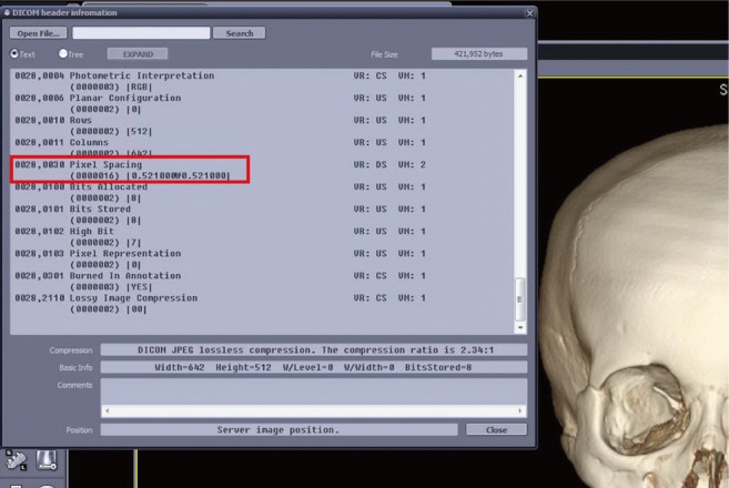
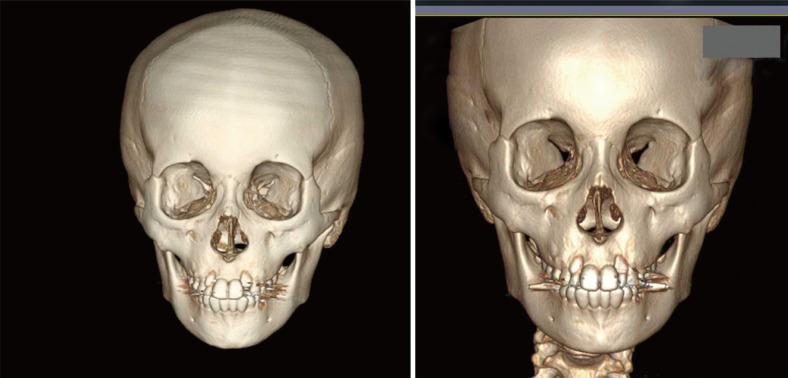
The patients' head was placed in the multi-slice CT (MSCT) scanner (Light speed 16, GE, Milwaukee, Wisconsin, USA) on a foam platform with the Frankfort horizontal plane parallel to the floor. Then, the patients' head was placed in the center of the MSCT scanner by ensuring that the midline light beam coincided with the mid-sagittal plane. The patients were told to bite their teeth in a centric occlusion. The MSCT scans were taken in the extended height mode (120 kVp, 300 Ma, Helical mode, field of view: 227.00 mm). Then, the 3D model of each head was constructed from the MSCT data using Aquarius iNtuition (TeRarecon, San Mateo, CA, USA). These reconstructed 3D models were used to perform the cephalometric analysis.
Cephalometric landmarks and measurements
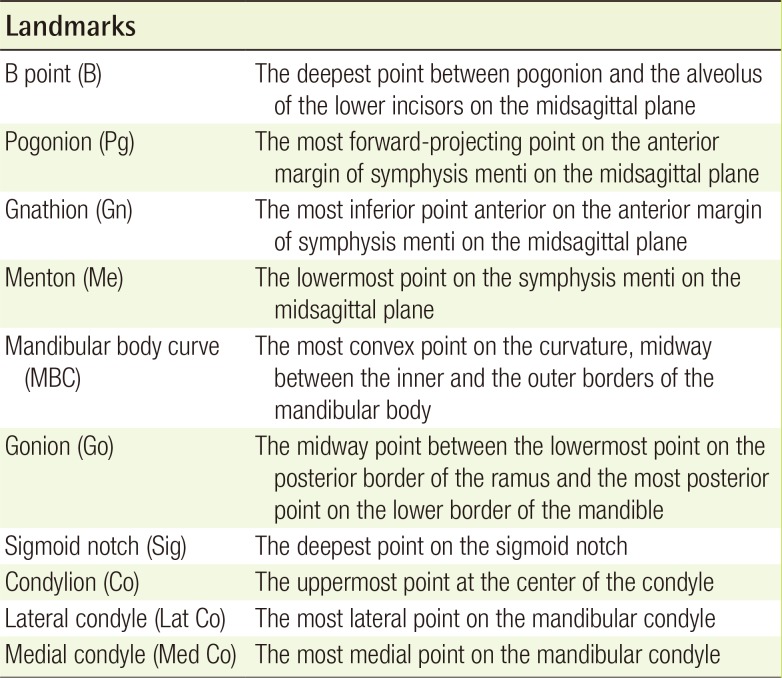
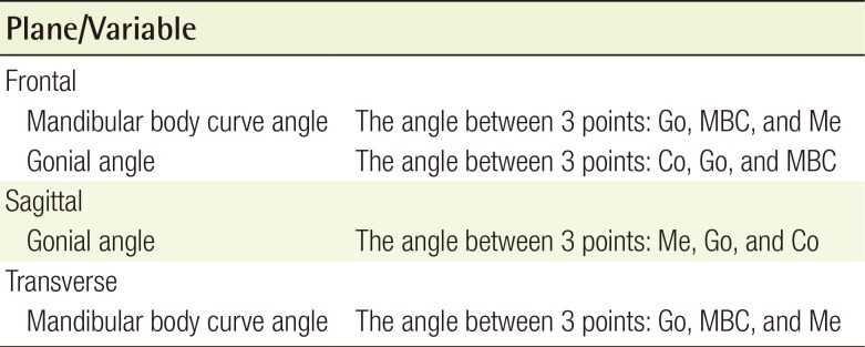
To minimize the identification error in placing the landmarks and obtaining the measurements, the same operator measured them three times at two-week intervals according to their definitions. The detailed definitions of the landmarks used are provided in Table 1. Four angular measurements were obtained using 3D CT imaging for the current study. These measurements were averaged for further statistical analysis. The measurements obtained are presented in Table 2. The Viewbox software (Marosis M-view 5.4, Infinitt Technology, Seoul, Korea) was used to identify conventional cephalometric hard-tissue landmarks and to measure the distance and the angle in each dimension (Figs. 1, 2, 3). The data were analyzed to compare between the left and the right sides, and between men and women.
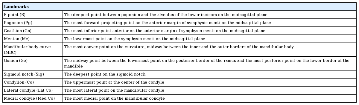
Definitions of cephalometric landmarks
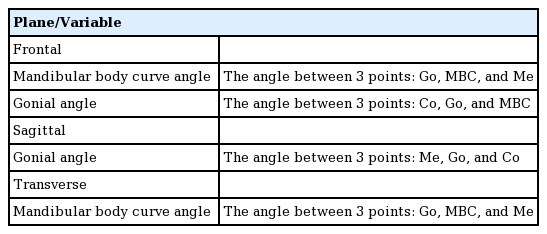
Definitions of cephalometric measurements
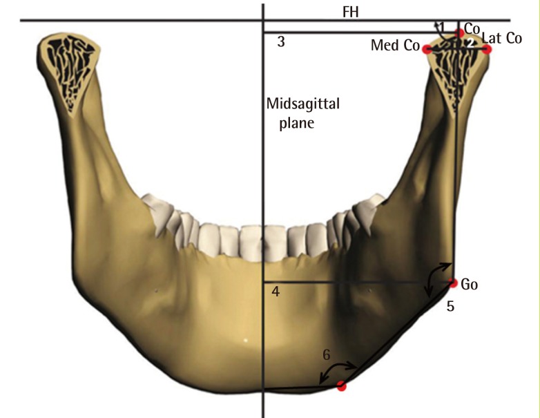
Schematic representation of frontal landmarks and measurements
FH, Frankfort horizontal plane; Co, condylion; Med Co, medial condyle; Lat Co, lateral condyle; Go, gonion; 1, ramal mediolateral inclination; 2, condylar width; 3, condyle to midsagittal plane; 4, gonion to midsagittal plane; 5, gonial angle; 6, mandibular body angle.
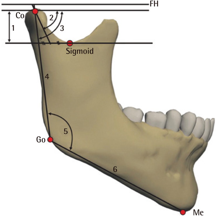
Schematic representation of sagittal landmarks and measurements
FH, Frankfort horizontal plane; Co, condylion; Go, gonion; Me, menton; 1, condylar height; 2, condylar anteroposterior inclination; 3, ramal anteroposterior inclination; 4, ramal length; 5, gonial angle; 6, mandibular body length.
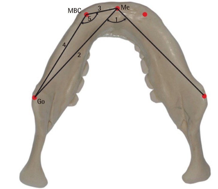
Schematic representation of transverse landmarks and measurements
Me, menton; MBC, mandibular body curve; Go, gonion; 1, menton angle; 2, mandibular body length; 3, anterior mandibular body length; 4, posterior mandibular body length; 5, MBC angle.
Statistical analysis
A statistical analysis was carried out using IBM SPSS ver. 21.0 (IBM Corp., Armonk, NY, USA). Linear and angular variables were expressed as mean±standard deviation. In addition, a paired t-test was used for comparing the obtained variables between the two sides, and an independent t-test was used for comparing the obtained variables between the two sexes.
A P-value of <0.05 was considered statistically significant.
RESULTS
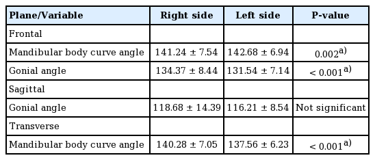
Comparison of measurements between the two sides
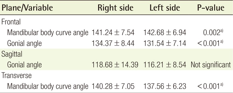
The frontal measurements revealed that both the mandibular body curve angle and the gonial angle showed a statistically significant difference between the right and the left sides (P=0.002 and P<0.001, respectively).
The mandibular body curve angle was larger on the left (Lt) side (right [Rt], 141.24±7.54; Lt, 142.68±6.94; P=0.002), and the gonial angle was larger on the right side (Rt, 134.37±8.44; Lt, 131.54±7.14; P<0.001).
The sagittal measurements showed that the gonial angle was larger on the right side without any statistical significance (Rt, 134.37±8.44; Lt, 131.54±7.14; P>0.05).
The transverse measurements revealed that the mandibular body curve angle showed a statistically significant difference between the right and left sides (P<0.001). The mandibular body curve angle was larger on the right side (Rt, 140.28±7.05; Lt, 137.56±6.23; P<0.001) (Table 3).
Comparison of measurements between the two sides
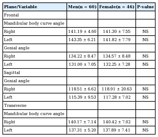
Comparison of measurements between the two sexes
The frontal measurements revealed that the gonial angle was larger in women, with no statistical significance.
The mandibular body curve angle did not exhibit a statistically significant difference between men and women.
The sagittal measurements showed that women had a larger gonial angle and there was no statistically significant difference between men and women.
The transverse measurements revealed that there was no statistically significant difference in the mandibular body curve angle between men and women (Table 4).
Comparison of measurements between the two sexes
DISCUSSION
The mandible is a key anatomical structure from both functional and aesthetic perspectives [16]. Patients with mandibular asymmetry or deformity can obtain satisfactory aesthetic outcomes from mandible surgery such as mandible angle reduction, corticectomy, or genioplasty. Considering the 3D configuration and curvature of the mandible and its involvement in dental occlusion, it is mandatory to preoperatively measure the standard cephalometric parameters in these patients [17].
Conventional 2D cephalometric analysis has long been used for measuring key cephalometric landmarks and measurements [18]. The current standard is to use plain lateral and frontal cephalograms for a 2D cephalometric analysis. However, there are well-known limitations to 2D imaging, such as projective displacement, rotational errors, and linear projective transformation, which interfere with the reliability and reproducibility of these measurements [619]. Moreover, most 2D measurements are distorted in the presence of facial asymmetry [20]. A 3D cephalometric analysis has been proven to have some benefits over a 2D analysis, including higher reproducibility [1213]. Therefore, we focused on pooling 3D cephalometric measurement data for Korean individuals for further use in craniofacial or orthognathic surgery. We focused on the measurement of the mandibular body curve angles and gonial angles in the frontal view.
Frontal cephalometry has not been routinely performed to make a treatment plan for patients with mandibular deformity. Many structures are superimposed over each other in frontal cephalograms, making it difficult to accurately indicate the landmarks and make measurements. However, this problem can be overcome by using 3D CT images, as the structures are not all superimposed on a film but laid out in a 3D space [21]. The additional information obtained from a frontal cephalometric analysis includes the asymmetry of the mandible and the jaw width, which was considered relatively useless. However, when performing aesthetic surgery, this information is valuable for achieving jaw symmetry [13]. In particular, frontal cephalometry is essential for patients with square jaws who are scheduled to undergo mandibular chin-body ostectomy and corticectomy. There have been reports of a cephalometric analysis of the mandible length and the gonial angle in the lateral view of 2D CT [22]. However, in the lateral view, it is difficult to evaluate the degree of harmony between the craniofacial structures on the basis of the width and the length of the face, and the frontal view is valuable in this regard [23].
Compared to the many previous studies using CBCT to acquire 3D imaging for a cephalometric analysis, MSCT was used in this study. Although the advantage of CBCT may be its availability for use by a dentist or an orthodontist without the need for a radiologist, the images acquired from MSCT are more precise with less distortion [24]. It is perfectly capable of obtaining high-quality images for a cephalometric analysis; however, it has one disadvantage: it exposes the patient to more radiation than CBCT [21].
From the statistical analyses, in the Korean population, the gonial angle was statistically significantly larger on the right side in the frontal view, and the gonial angle was larger on the right side in the sagittal view, although this was not statistically significant. This indicates that the right gonial angle is larger in Koreans, with asymmetry present in general. Therefore, for plastic and orthodontic surgery, surgeons should consider the asymmetry of both sides in order to control symmetry.
In the gender-based comparisons, no statistically significant difference was observed, but the gonial angle was larger in women in both the frontal view and the sagittal view, which contradicts the fact that the mandibular bony structure is generally more angulated in men than in women. More studies are necessary to investigate this relationship in the future.
As this is one of the early studies on the accumulation of 3D cephalometric measurement norms, further studies on the topic are necessary. It is important to analyze the relationship between bony structures and the soft tissue, as the shape of the underlying bony structure and how the overlying soft tissue is formed may differ between individuals. Moreover, further study is needed to compare the cephalometric measurements between Koreans and other ethnic populations.
In summary, we performed a 3D cephalometric analysis of the angular measurements of the mandible in Korean individuals.
The significance of this study lies in presenting an average of the mandibular angular measurement in Koreans using 3D CT of the mandibular angles, which are difficult to measure in 2D and are needed to develop a standard for determining surgical patient groups and outcome evaluations in mandible contour surgery in the future.
Notes
No potential conflict of interest relevant to this article was reported.